· LS & JS · English · 6 min read
EL vs. PL - Two paths to PV module quality inspection
EL vs. PL for PV modules: A concise comparison of daylight photoluminescence and electroluminescence for detecting microcracks, shunts, and degradation.
Mini-Glossary
| Term | Short explanation |
|---|---|
| Luminescence | Light emission of a solar cell when many charge carriers recombine (for silicon: near-infrared range). |
| EL | Luminescence via electrical excitation: the module is driven in forward bias. |
| PL | Luminescence via optical excitation: e.g., laser/LED in lab setups or sunlight in the field. |
| Daylight PL (DPL) | PL in field conditions: sunlight excites the cells. The weak PL signal is separated from background sunlight by comparing two operating points. |
| (DaySy) Daylight EL | EL in daylight: the luminescence signal is robustly extracted from ambient light via modulation + lock-in. |
| Shunt / Hotspot | Local defect path (low parallel resistance) and/or thermally critical area under operation. |
| PID / LeTID / UVID | Degradation patterns that appear as characteristic brightness distributions in luminescence images. |
How we compared EL and PL 1:1:
- Environment: backyard / realistic field conditions
- Distance: approx. 2 m
- Optics: 12 mm lens
- Camera: DaySy Cam (5 MP)
- Irradiance: approx. 800 W/m2
- Capture: sequential, same perspective, same scene
- EL: electrical excitation at I approx. Isc
- PL: daylight PL near open-circuit (sun as excitation source)
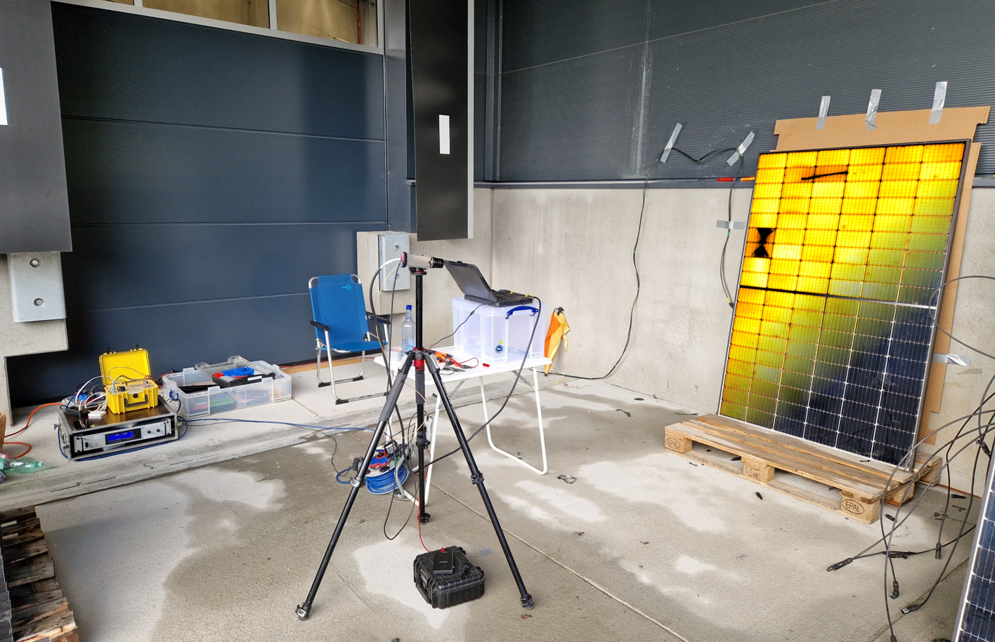
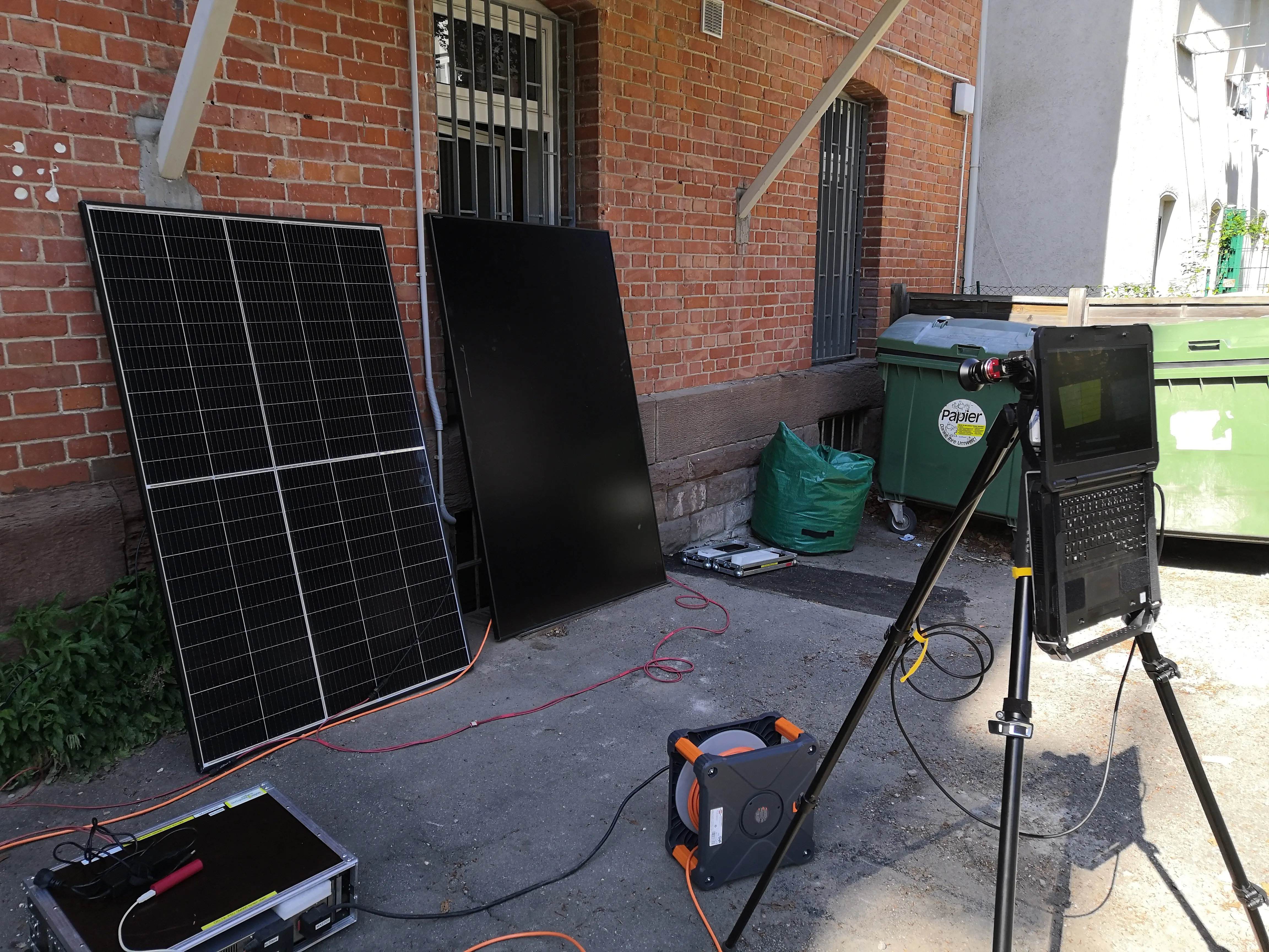 Figure 1: DaySy setup in a backyard field test (example measurement under realistic conditions).
1) Luminescence in 60 seconds
A solar cell can be thought of as a large LED: if you inject energy (electrical or optical), carrier density increases, and part of the carriers recombine radiatively, emitting light. Therefore, in luminescence images:
- bright -> locally favorable conditions for recombination/voltage
- dark -> less local luminescence (with potentially different root causes)
Important: “dark” does not mean the exact same thing in EL and PL, because each method operates under different electrical boundary conditions.
2) Electroluminescence (EL): a view of current paths
In EL, the module is driven in forward bias. Current flows through metallization, interconnectors, and contacts - and that is exactly why EL is so informative:
EL is especially strong for
- contact/current-path issues (finger interruptions, solder joints, interconnects)
- electrically active cracks and local decoupling (often with strong contrast)
- shunts
- degradation patterns (e.g., PID/LeTID/UVID)
Typical practical hurdle: EL requires a power source and safe procedures for DC voltages/currents. In field operations, this can quickly increase logistical effort (access, safety, possible external power supply).
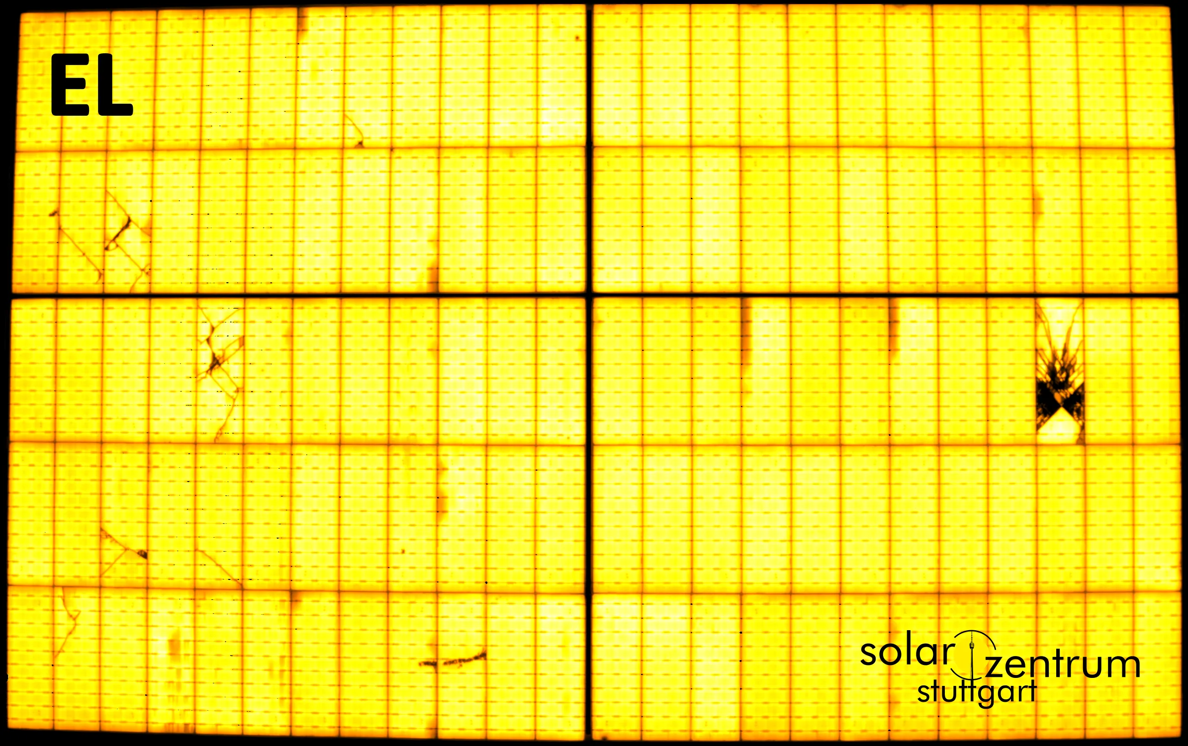 Figure 2: EL image (example). Visible are microcracks, splinter fractures, and scratches.
3) Photoluminescence (PL): the fast daylight view
PL uses optical excitation:
- Lab PL: laser/LED, often cell- or wafer-level, highly controlled.
- Daylight PL (field): sunlight provides excitation.
The key field challenge: the PL signal is much weaker than reflected sunlight. Therefore, daylight PL typically records at least two images at different electrical operating points and combines them so the luminescence component remains.
In practice this means: no direct module contact / no disconnecting individual modules, but typically access to string/inverter controls (or switching equipment) to safely change operating points.
Operational advantage: daylight PL usually requires no high-power generator for back-biasing (typically no 20 kW generator, often used in classical field EL). This makes PL highly attractive as a screening tool, especially in large plants.
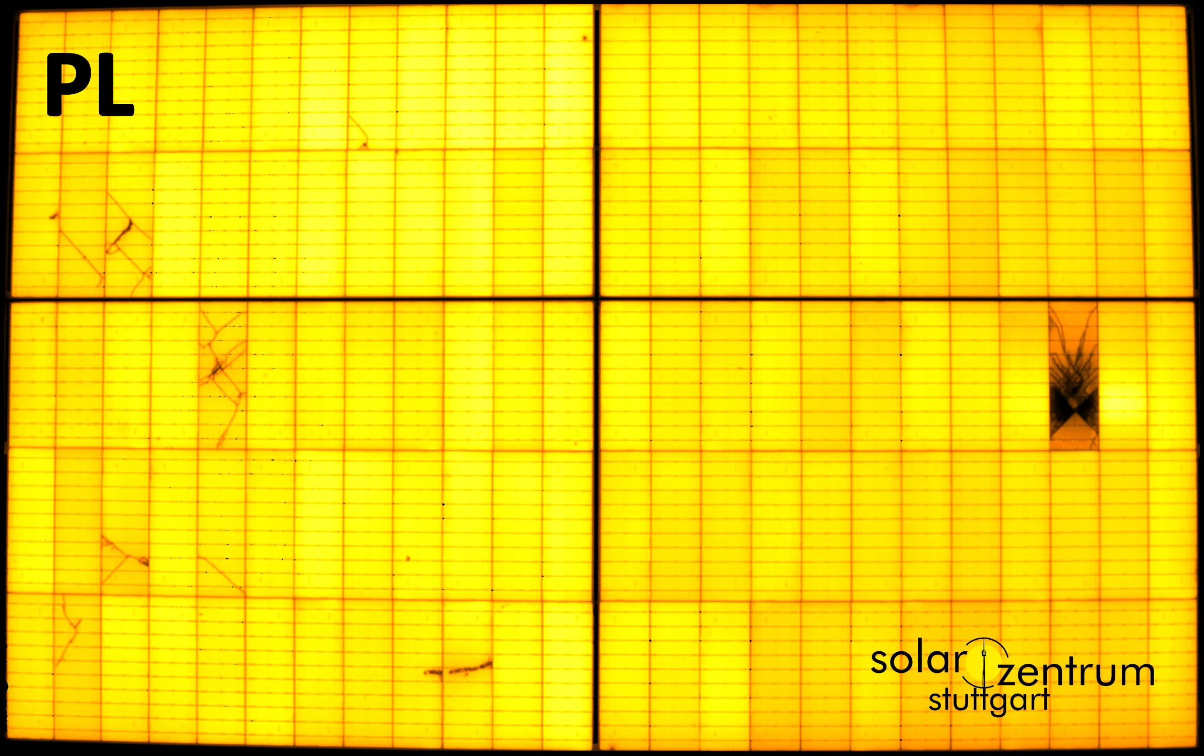 Figure 3: PL image (example). Microcracks/splinter fractures/scratches are also clearly visible.
4) What does “dark” really mean?
A common misunderstanding in customer discussions is expecting that “dark = defective” can be interpreted identically in all methods.
- EL (forward current, e.g., approx. Isc): dark regions often occur where current paths are hindered (contact issues, series resistance) or where shunts pull down local voltage.
- PL (near open circuit): dark regions are mainly where local voltage drops due to recombination losses or shunts.
Both methods show “less luminescence” - but the dominant cause can differ.
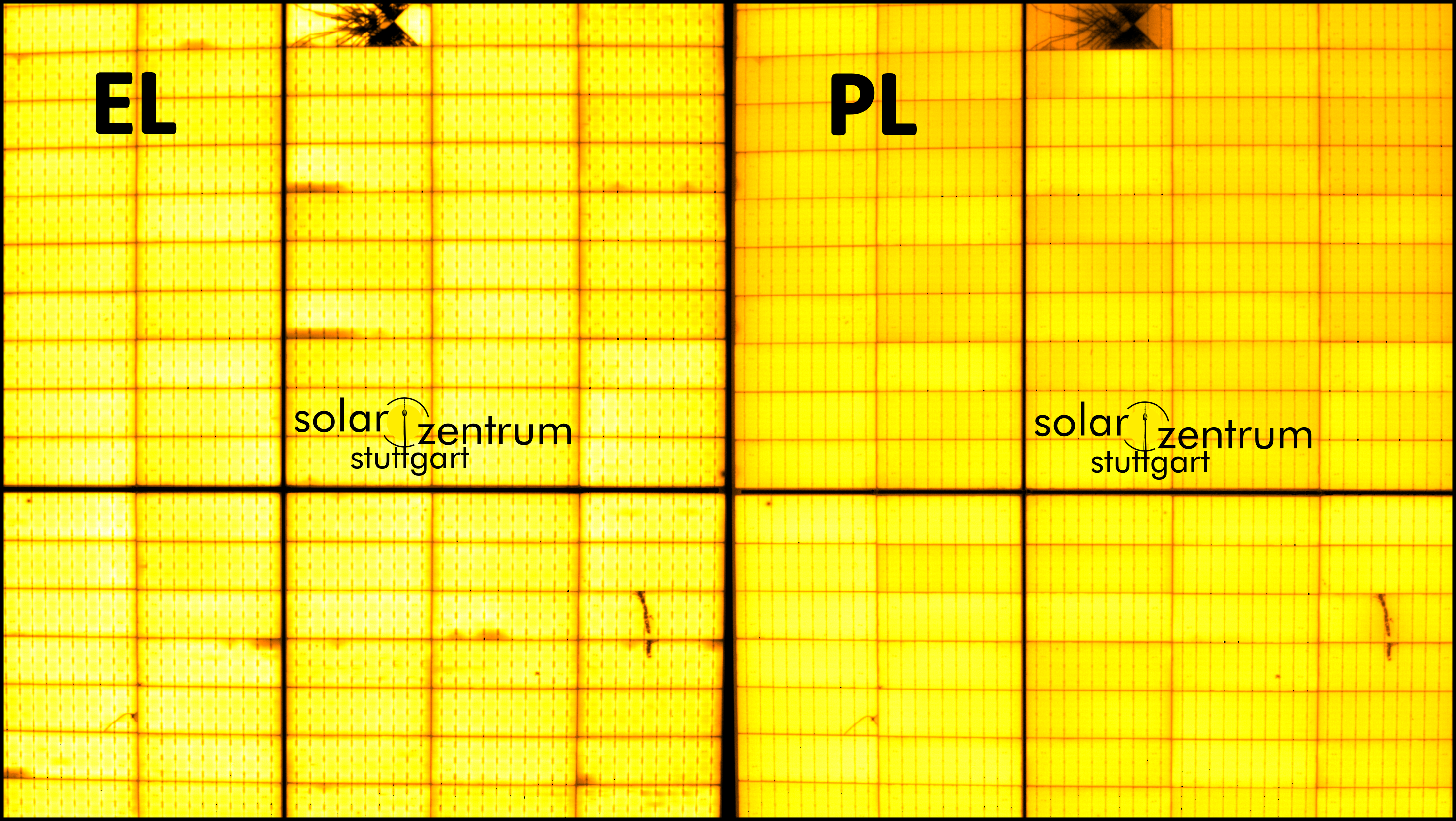
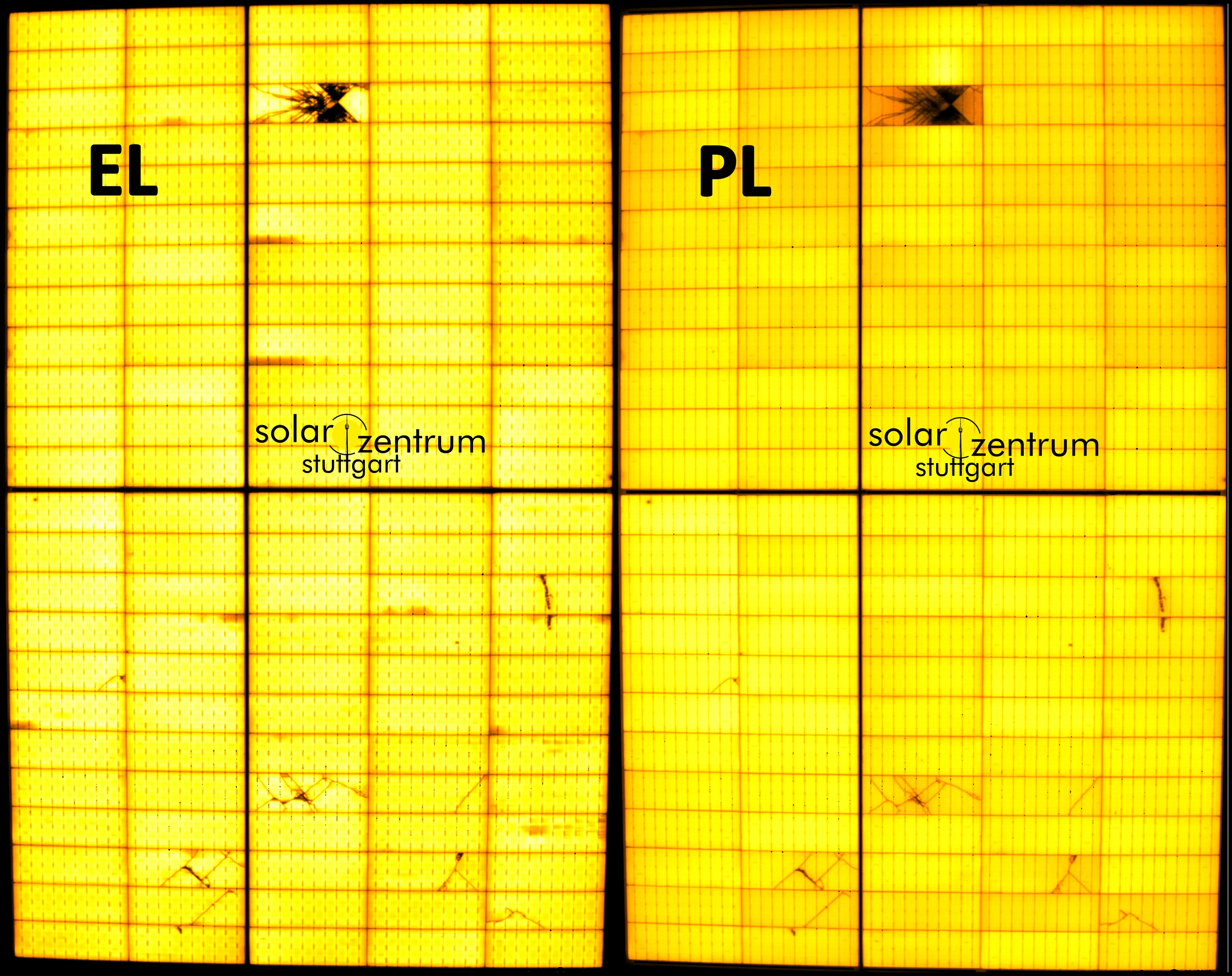 Figure 4: EL on the left, PL on the right - both show microcracks, scratches, and splinter fractures.
Takeaway:
For external mechanical stress events (transport, installation, snow/hail loads), both methods often provide very similar diagnostic value.
5) Who sees what?
PL is the “hero” for:
- microcracks (mechanical damage)
- PID/LeTID/UVID (degradation patterns)
- shunts/hotspots (often very visible in PL, especially with splinter fractures)
EL is the “hero” for:
- finger interruptions / metallization issues
- solder-joint/interconnector problems
- bypass-diode topics / substring effects
Both are strong for:
- mechanical cell damage (microcracks, splinter fractures, scratches)
- many shunt/hotspot signatures (depending on operating point and measurement setup)
6) “When EL, when PL?” - a decision aid
| Use case | Recommendation | Why | Typical findings |
|---|---|---|---|
| Post-shipment inspection (PSI) | PL (installed), EL (pallet) | Fast, low logistics | Transport/handling damage, early degradation patterns |
| Post-installation acceptance / SAT | PL | Installation and transport drive mechanical damage | Microcracks |
| O&M screening (operation) | PL | Efficient over large areas, daytime capable | Degradation patterns, mechanical anomalies, shunts |
| After event (hail, storm, snow) | PL | Insurance relevance: identify external impact effects | Impacts, splinter fractures |
| Claim/dispute cases | Combination (with defect catalog) | Robust argumentation requires comparison + standardized terms | Defect classes, evidence, documentation |
| Root-cause / forensics | Combination | Interaction of contact issues, shunts, and cracks | Microcracks, degradation, manufacturing defects |
7) DaySy: daylight EL with PL capabilities
The DaySy system was developed to make luminescence imaging robust in daylight:
- With DaySy EL, a modulated electrical signal is applied; camera/software reliably extract luminescence via lock-in from bright ambient light.
- DaySy can also support PL workflows (daylight PL via operating-point switching) - internally often called DaySy PL - ideal for fast screening.
In short: no need to wait for darkness - we can apply EL and/or PL in the field depending on the diagnostic question.
8) Analysis: AI-supported, always human-in-the-loop
We use AI for pre-classification / pre-labeling to structure large data volumes quickly.
What matters:
- Human-in-the-loop: outputs are reviewed and curated by experts.
- Triple-check voting for pass/fail borderline cases.
- Defects are documented according to an agreed defect catalog (clear naming; on request aligned with common nomenclatures such as VDE SPEC 90031).
Quantification outlook: research indicates that, with suitable operating points, daylight EL can even support performance-sensitive assessments (e.g., series-resistance-related losses).
9) Typical service packages
Screening (fast, large-scale)
- Goal: identify suspicious areas/modules
- Deliverables: image dataset + defect heatmap + priority list (A/B/C)
Forensics (when the question is truly “why?”)
- Goal: root-cause clarification (transport, installation, weather, degradation)
- Deliverables: detailed report with defect classes, image evidence, and context-based plausibility checks
Post-event / claim support (hail, storm, snow)
- Goal: robust documentation for technical and insurance decisions
- Deliverables: event report, damage overview, evidence package (images, classification, rationale)
Conclusion
- EL remains the strongest method for contacting/current-path issues and “electrical” interpretation.
- Daylight PL is often the fastest route to large-scale screening of mechanical damage and degradation patterns - without the logistical overhead of classical field EL.
- For acceptance, claims, and damage assessment, combining both methods is often the most robust approach.
If you want to know what is really happening in your PV system: we measure in daylight - and we deliver decisions, not just images.
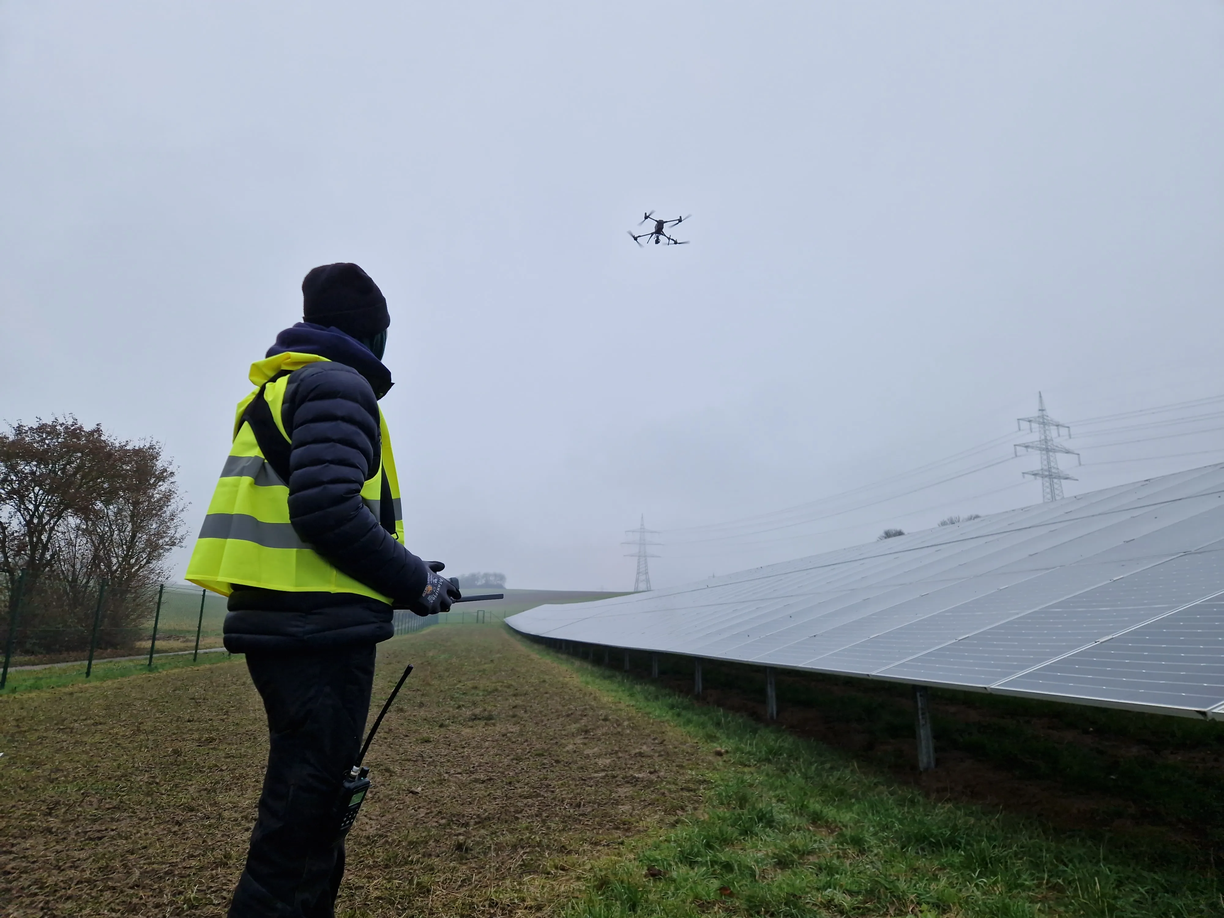
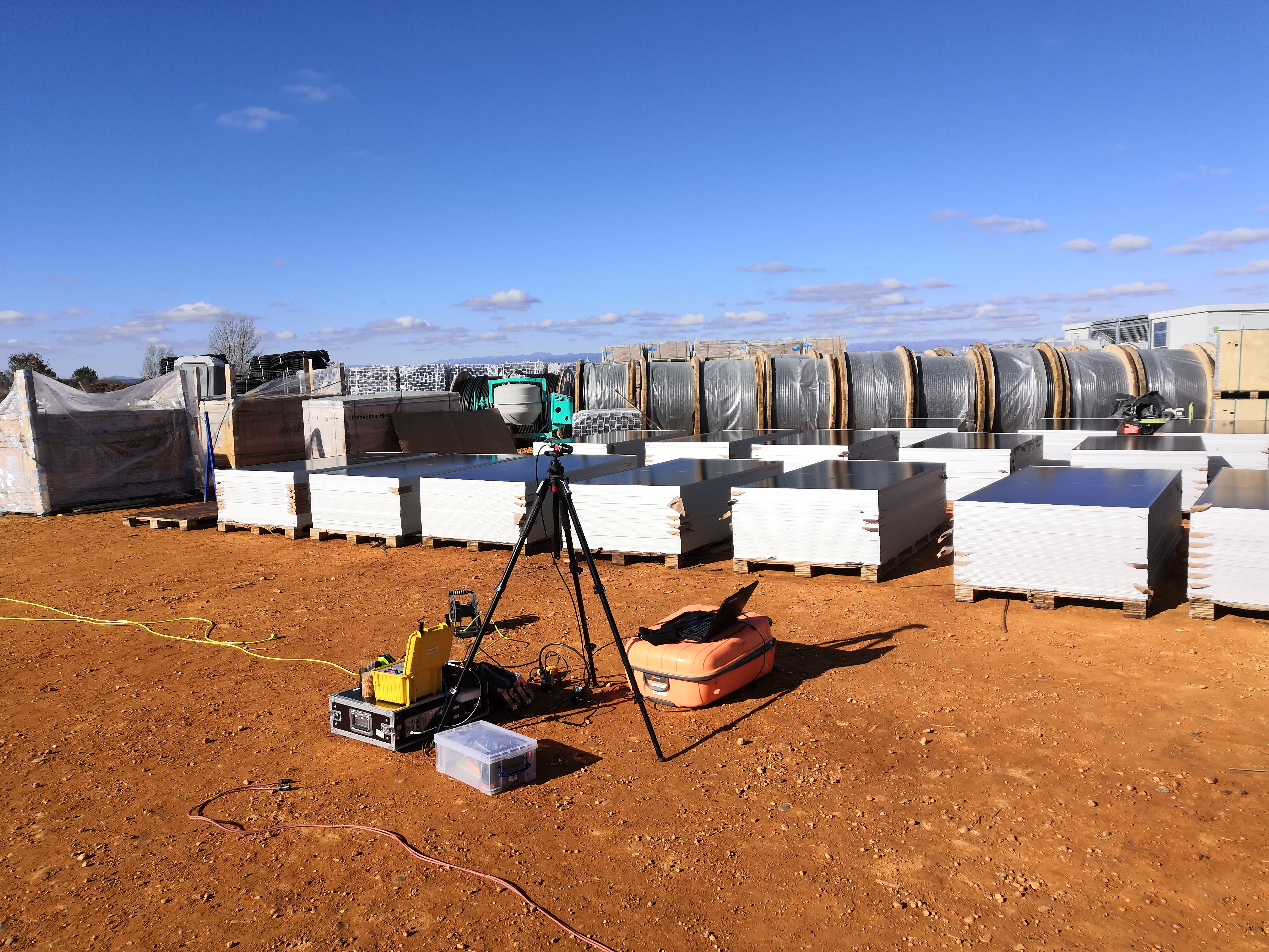
Figure 5: Example of a field luminescence measurement performed by Solarzentrum Stuttgart using a drone.
Fine print (important)
Luminescence images are a snapshot in time. Statements about yield impact/forecast are only robust with context (e.g., IV data, temperature, irradiance, plant history). Defect evaluation depends on the agreed defect catalog and expert interpretation. Work on PV strings/plants must only be performed by qualified personnel.References
- L.-M. Stoicescu, Bildgebende Messung der Lumineszenz von Photovoltaikanlagen unter Tageslicht, Dissertation, Universitat Stuttgart, 2019.
- VDE SPEC 90031 V1.0 (en), Electroluminescence (EL) of photovoltaic modules - Terms and classification, 06.01.2025.
- H. Gottlieb et al., Power Losses From Series Resistances-Analysed Using Daylight Photoluminescence Imaging, Progress in Photovoltaics: Research and Applications, 2025, doi: 10.1002/pip.70022.
- Solarzentrum Stuttgart GmbH, DaySy EL - Operation Manual, Rev. Sept. 2023 (available on request).
- Solarzentrum Stuttgart GmbH, Defect Catalog for Electroluminescence Measurements (available on request).