· JS · English · 7 min read
Drone-Based PV Inspection for Hail Damage
Our inspections north of Zurich and in St. Johann: We use daylight EL/PL to inspect PV systems for microcracks in solar modules and document the findings in layout plans and inspection reports.
Glass breakage and cracks in the silicon wafer
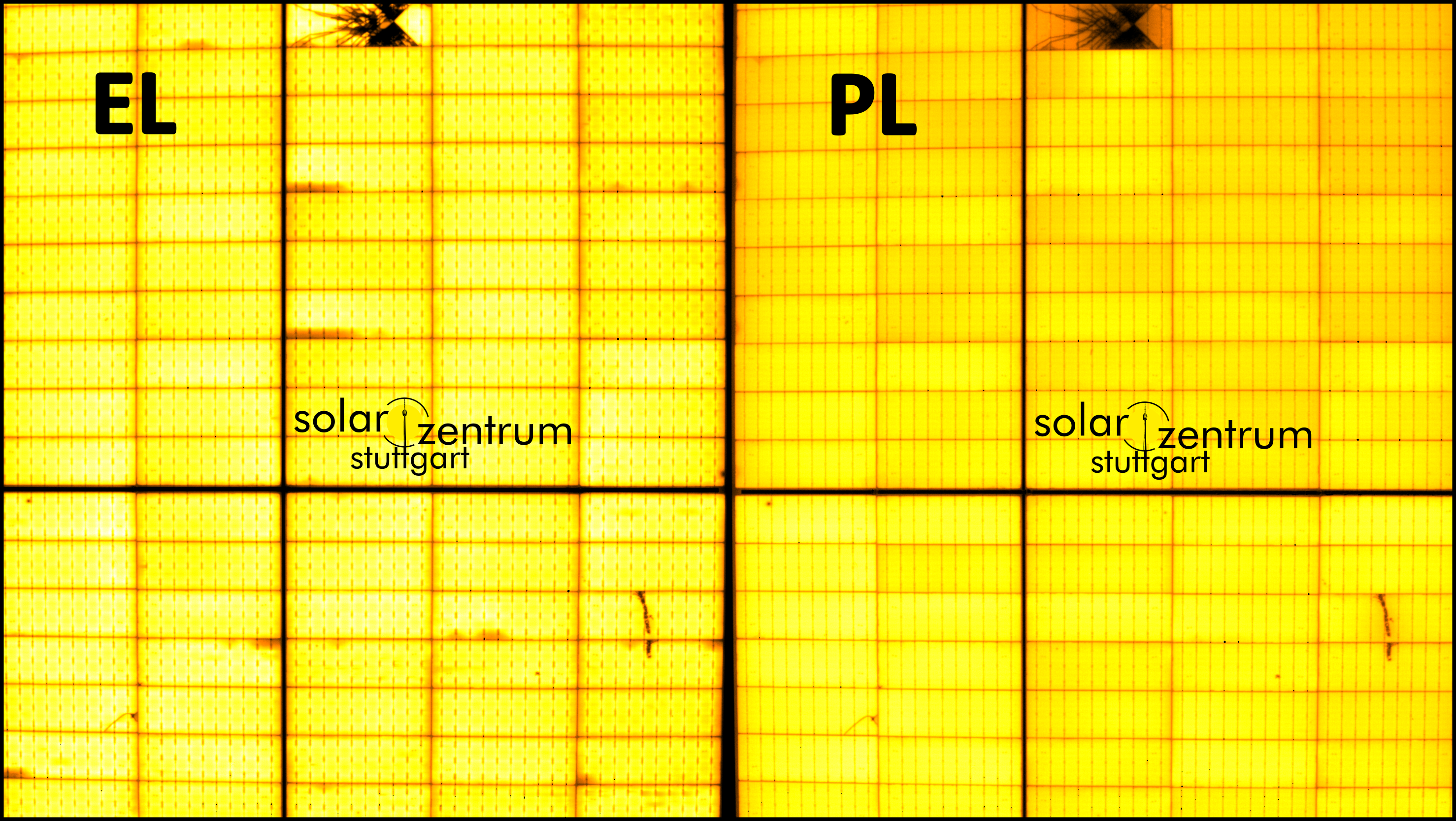
During our hail damage inspections in 2026, we examined both visible glass damage and mechanical damage to silicon solar cells. A cell crack is a fracture in the crystalline silicon wafer from which the solar cell is made. Such cracks can occur even when the front glass remains intact and may initially cause no noticeable yield loss. Thermal and mechanical stress can cause microcracks to propagate. Severe crack patterns can lead to local heating (hot spots) and power losses.
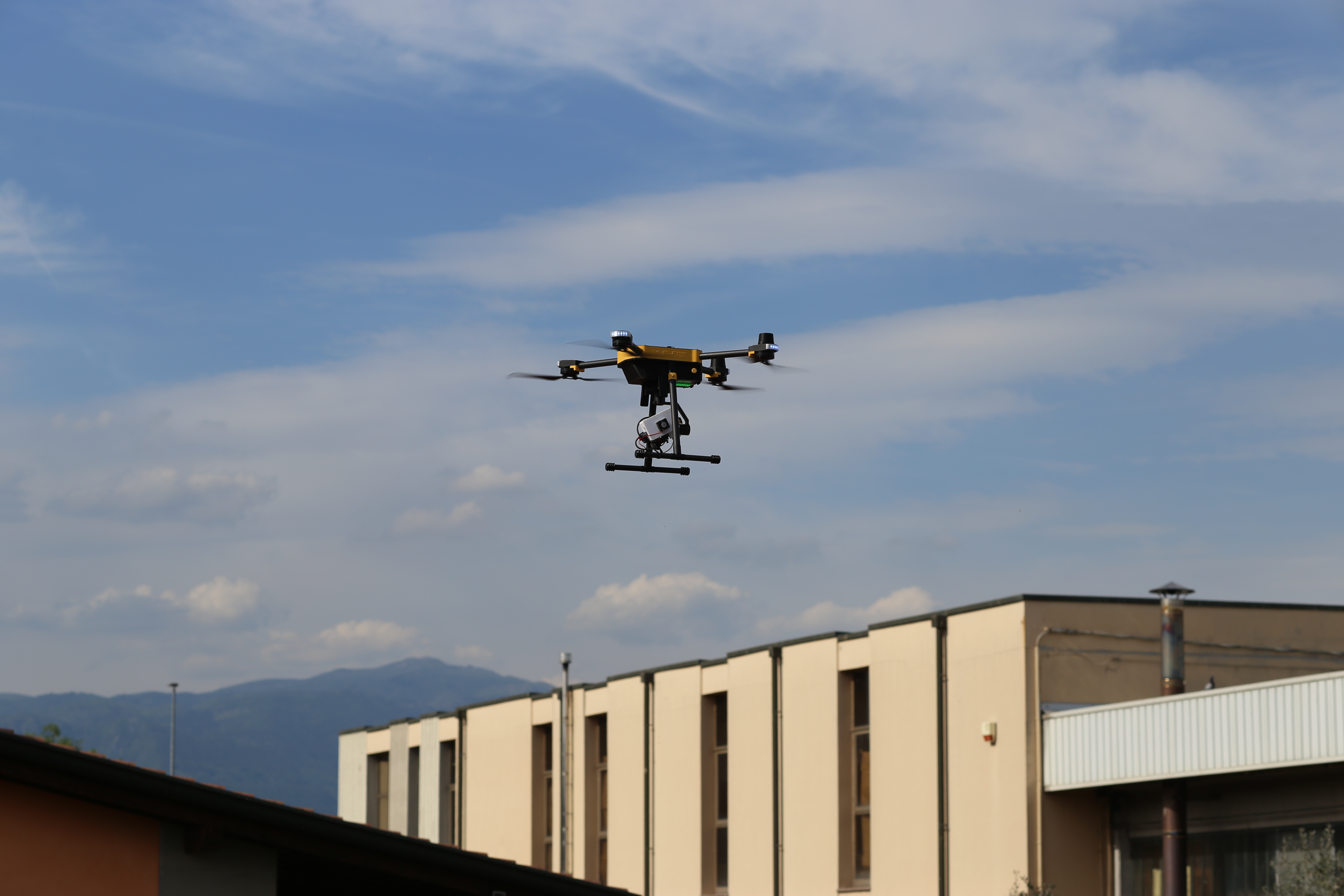
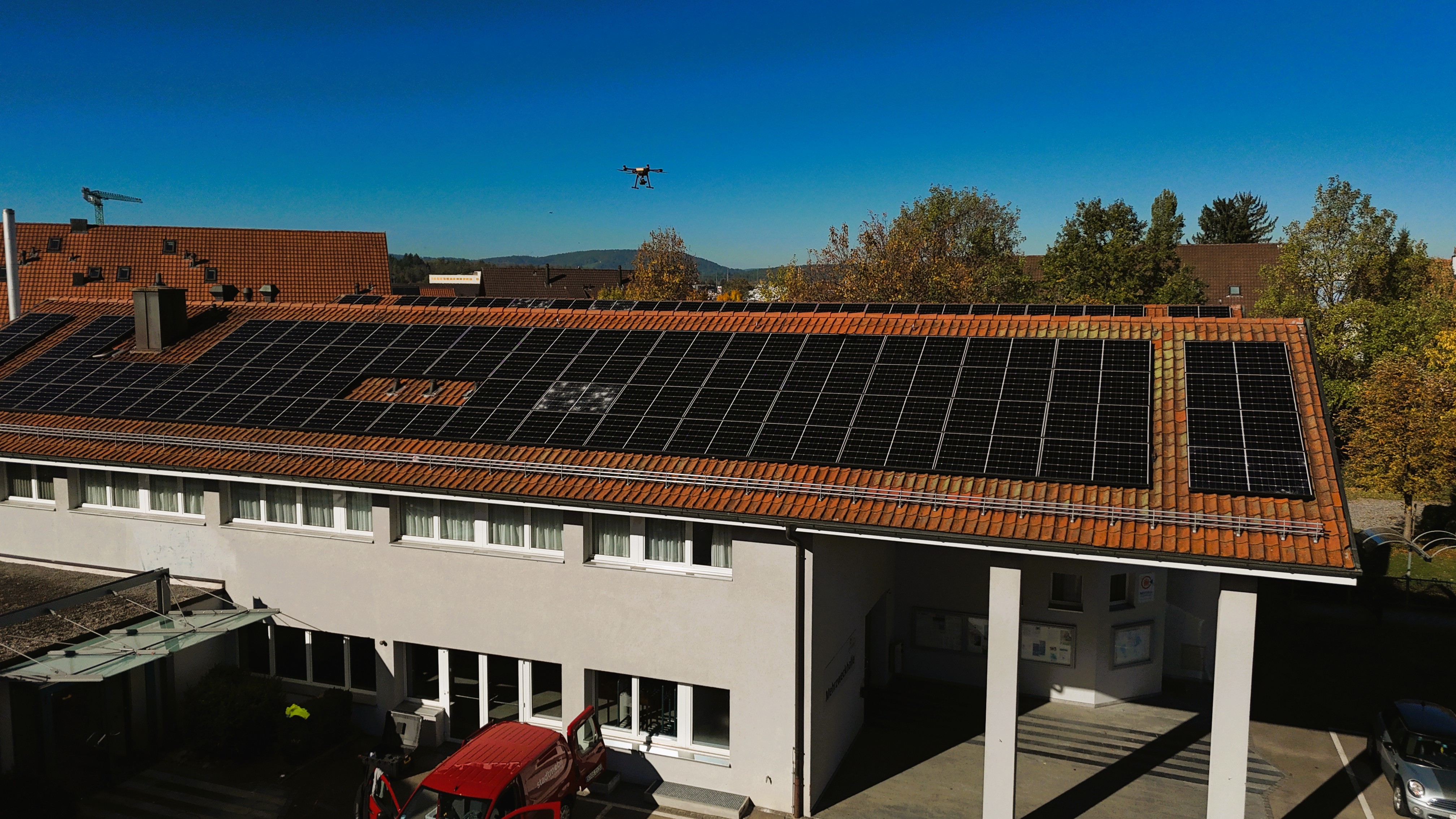
Together with our partners, we inspected rooftop PV systems north of Zurich and in St. Johann using drone-based daylight electroluminescence (EL) and photoluminescence (PL). We record crack patterns and anomalies in luminescence emission to assess the condition of individual modules.
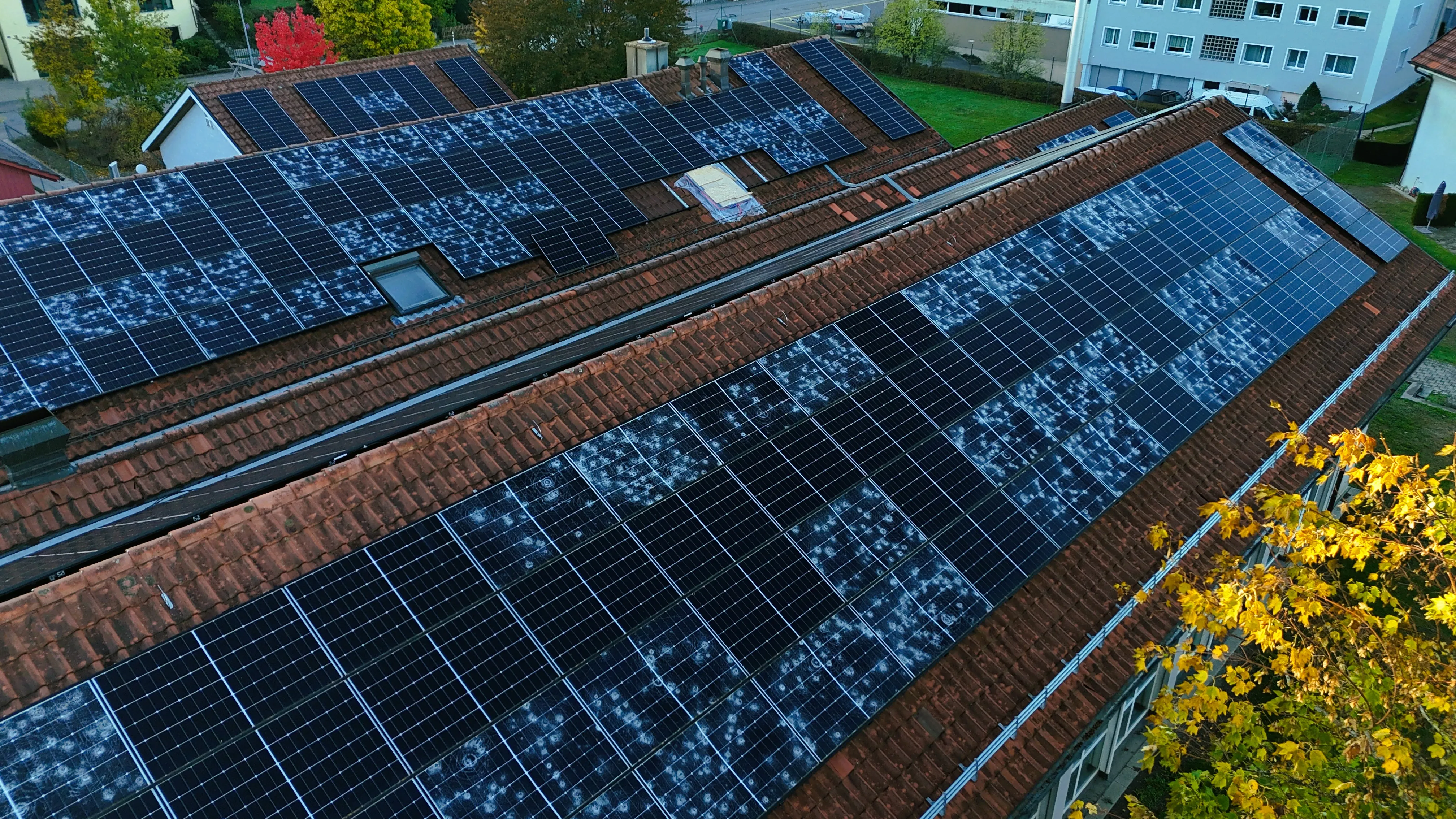
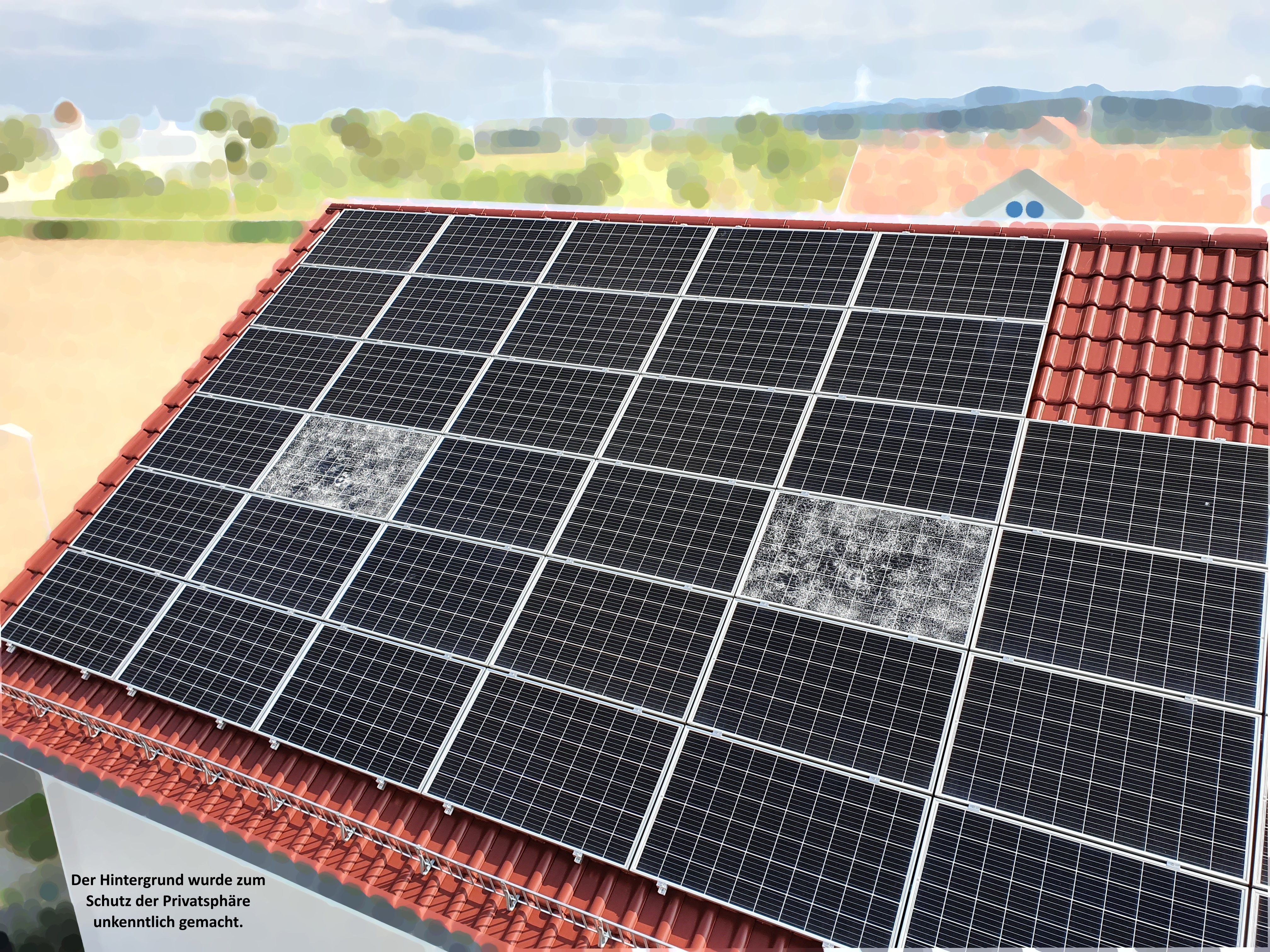
Rooftop system with extensive glass breakage. The apparently intact modules are particularly important to inspect.
Switzerland: inspections with Energie Netzwerk
North of Zurich, we worked together with Energie Netzwerk. Within one week, we inspected thousands of modules. Glass breakage on some modules prompted us to examine the remaining array for mechanical defects as well. Extending the inspection beyond the visible damage was essential.
Using the drone-mounted camera, we captured EL/PL images of the installed modules, which remain on the roof throughout the inspection. Our analysis considers crack morphology, the extent of affected cell areas and their distribution across the system.
Reliable documentation requires each image to be assigned to a specific module position. This allows us to combine visual findings with luminescence data and locate affected areas for further testing. We assess the electrical significance of a crack separately from its geometric shape.
The Swabian Alb near St. Johann: with ET Vöhringer
In St. Johann, we inspected hail-affected rooftop systems together with Energietechnik Vöhringer (ET Vöhringer). The local specialist contractor is an important contact for system documentation and site access. At every system equipped with glass-backsheet modules, we also found defects in modules without broken glass.
To assess whether a detected microcrack can be attributed to the reported hail event, we consider the system’s history, the spatial damage pattern and supporting findings. An individual luminescence image documents the condition at the time of measurement, but on its own establishes neither the cause nor when the damage occurred.
Processing and analysing luminescence images
A large part of the work lies in processing the recorded image sequences. To produce luminescence images suitable for analysis, we need to stabilise the individual frames and align them precisely. This motion correction is particularly important for drone imaging so that the same cell structures overlap in successive frames.
Our patented differential imaging method separates the weak luminescence signal from the superimposed daylight background. Stabilisation and differential image processing therefore provide the basis for subsequent defect analysis. In the processed images, we assess crack patterns and affected cell areas and mark the findings for documentation.

The coloured markings highlight single and branching cracks as well as crack patterns that isolate cell areas. The cracks indicate mechanical loading.
We combine the PL images of a string according to the actual module arrangement. This image layout shows the spatial distribution of the findings and allows neighbouring modules to be compared directly.
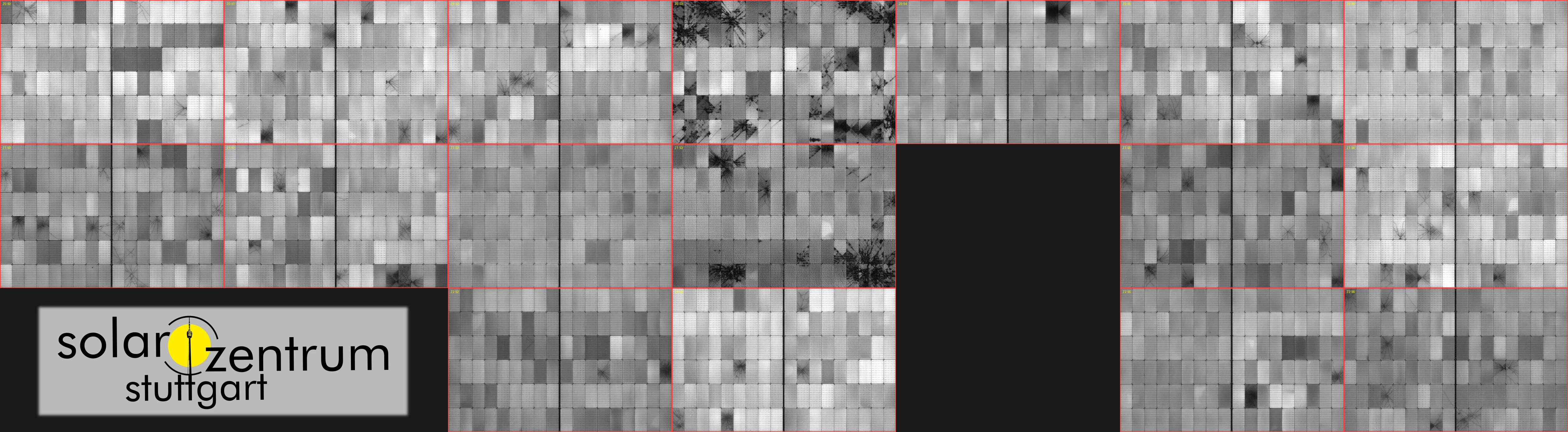
PL layout with module IDs: individual images in their respective positions within the rooftop array.
Assessing damage: Swissolar and VDE SPEC
The Swissolar photovoltaic factsheet No. 17 provides guidance on handling hail damage. It recommends a visual inspection after severe hail. Visible damage should be documented, the insurer notified and qualified specialists consulted. Where glass is broken or modules are severely deformed, the affected parts of the system should be taken out of service by qualified personnel. An insulation resistance test forms part of the safety assessment. Thermography can reveal hot spots, while yield monitoring helps track longer-term effects. Given the effort described in the factsheet, it recommends EL where there is a strong suspicion of damage. EL measurements enable a detailed assessment of cell condition based on crack patterns and electrically inactive areas.
A crack does not necessarily interrupt current flow completely. To assess its electrical significance, we also consider the cell’s electrical contacts and any potentially isolated cell areas. Visible crack length alone does not provide a reliable measure of power loss.
We use the terminology of VDE SPEC 90031 V1.0 (2025), sections 3.4 and 6: single cracks, double cracks, multiple crack patterns and dendritic (branching) crack structures. A complete crack starts and ends at the cell edge; an incomplete crack ends within the cell. Here, “complete” describes the crack path, rather than electrical isolation.
The SPEC provides a common classification of EL anomalies. It is not part of the VDE regulations and does not prescribe a universal module replacement rule. Further background is available in our article on EL inspection after hail.
Module classification and customer report
We enter the module assessments into the string layout plan. We use categories A to D based on the assessment scheme described in the Swissolar factsheet; G identifies modules with broken glass in our documentation. This module assessment is distinct from naming individual crack patterns according to VDE SPEC.
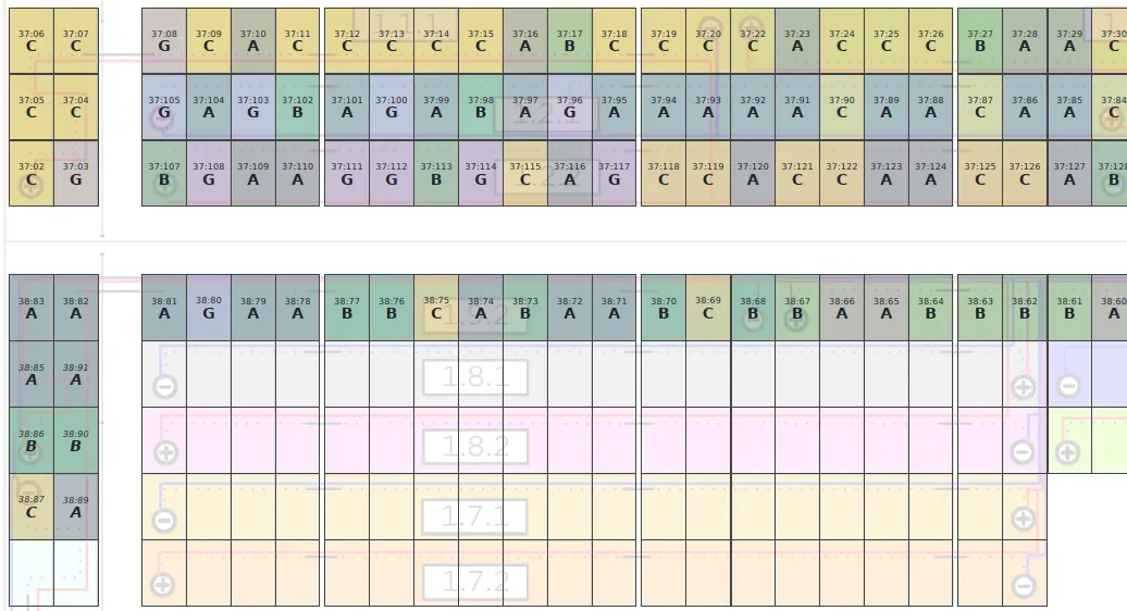
Extract from the assessed string layout showing categories A, B, C and G. The module IDs link the assessments to the inspection images.
In the customer report, we bring together the inspection scope, measurement conditions and distribution of assessment categories. Links to the inspection images and string layout make it clear which findings underpin the assessment.
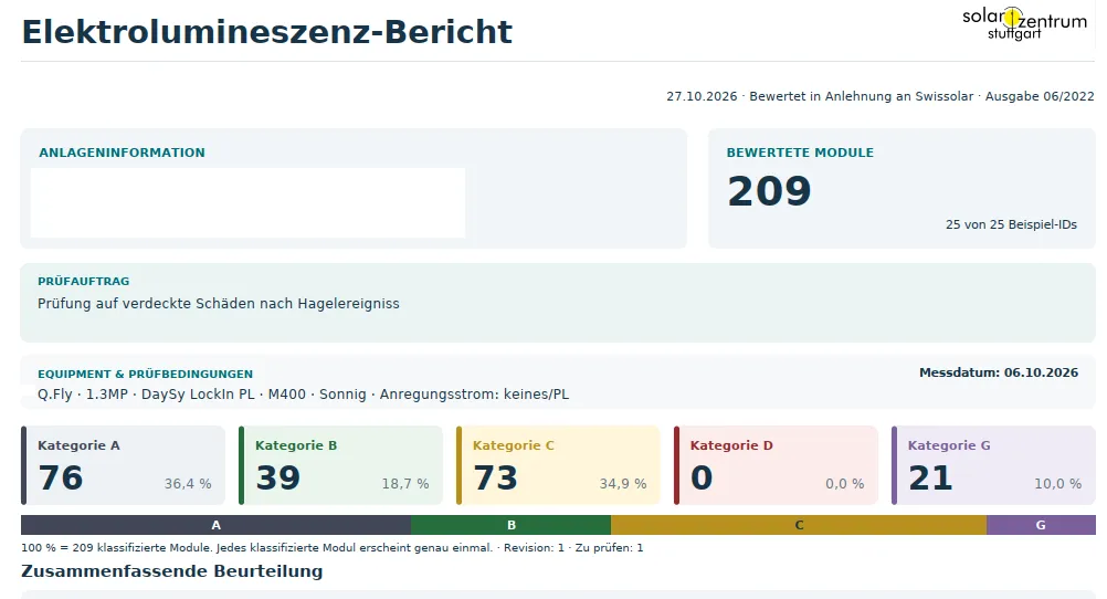
Extract from the report following luminescence analysis. The figures shown relate to the inspection documented in that report.
Measurement technology and ELFI funding
We combine our patented DaySy daylight method with drone-based imaging using the KUR-500 V2. For EL, we excite the solar cells electrically. This requires suitable electrical connections and current injection into the PV strings. PL uses optical excitation by sunlight and does not require an external power source. The two methods provide different contrasts depending on the defect type and measurement conditions; we explain the differences between EL and PL in a separate article.
The daylight method allows measurements during normal site access hours without a night-time appointment. We describe camera integration and test flights with the KUR-500 V2 in our article on our collaboration with UP Caeli.
Further development of our drone-based daylight electroluminescence is supported through ELFI – Electroluminescence Flight Inspection by the Stuttgart Climate Innovation Fund (SKIF) of the City of Stuttgart. The official project profile describes work on the gimbal, image stabilisation and automated analysis.
Next steps
Our inspections combine on-site measurements with module-level analysis. This gives operators and specialist contractors a basis for targeted follow-up tests on affected modules and for agreeing on the next steps.
If your PV system has been affected by hail, we will work with you to define a suitable inspection scope. Information on the process is available on our hail damage inspection page. You can reach us at hagel@solarzentrum-stuttgart.com.